The NodeMCU Platform
On this page I am going to talk about one particular combination of hardware and software that I think makes an economical and beginner-friendly platform for IoT experimentation, the NodeMCU platform.
The hardware - Espressif ESP8266 Wifi Modules
The ESP8266 is a tiny microcontroller chip invented by Espressif in China. It is intended for very low cost smart devices such as internet controlled light bulbs and power switches. There are a number of "compute modules" that combine the ESP8266 chip with some flash memory and power components to provide a postage-stamp-sized module that can be incorporated into larger circuits. Sometimes these modules are then mounted on a carrier board which adds more power circuitry and some switches. One of the most beginner-friendly is the reference design from the NodeMCU project. The "NodeMCU Developers Kit" (DevKit) is an open-source design that is available from a number of manufacturers for under $5 (more about this below).
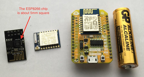 Above: Two different ESP modules (left) and a NodeMCU DevKit board consisting of module plus extra circuitry (right)
The software - NodeMCU
The NodeMCU project provides a firmware distribution for the ESP8266 modules. The term "firmware" is used to describe software that you program into hardware just once (get it? It's in between hardware and software. Engineers didn't get out much before computers became cool). You can think of the NodeMCU firmware as a very simple operating system for the module environment; you combine the standard firmware with your custom-written application software to solve some particular problem.
The NodeMCU firmware is written in C, but provides an environment for you to upload and run application programs written in Lua (an easy to learn scripting language). So all the hard C programming has been done, meaning you (the beginning IoT programmer) can work in the much more friendly Lua language. To use NodeMCU, you must install the NodeMCU firmware on your device just once, after that you can simply uload programs written in Lua into the device's flash memory over a USB cable, to make the device do whatever is desired.
The NodeMCU project also provides the reference hardware design for their Development Kit board, which is ideal for running the firmware, but the firmware itself will run on almost any ESP8266 module, not just the ones based on the reference design.
The WeMos D1 and D1 Mini boards are another design that is ideal for use with NodeMCU.
The NodeMCU development kit board gives you around 10 general purpose IO pins, WiFi wireless ethernet, asynchronous serial port, plus a USB socket for power and for uploading software to the device. Other ESP8266 modules may have more or fewer IO pins. You can add bluetooth if desired by connecting a bluetooth module to the asynchronous serial pins. You can also store files in whatever whatever space in your module's flash memory is left-over after the firmware and your application software are uploaded. The NodeMCU DevKit board has 4MB of flash memory, of which around 3MB remains available after installing the firmware.
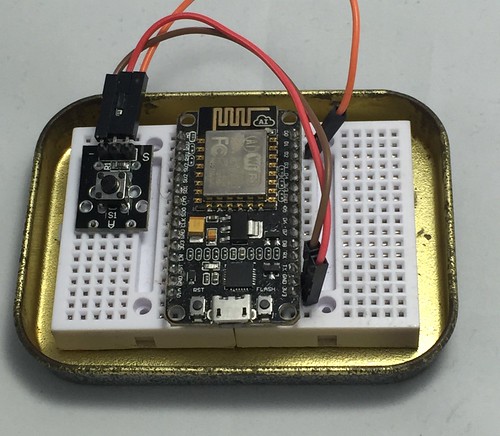
The NodeMCU DevKit board has a blue light-emitting-diode (LED) connected to pin D4, and a push button (labelled "Flash") connected to pin D3, so if you want to dip your toe into IoT for the least amount of money, you could buy the DevKit board and nothing else, powering it by USB cable from your computer or from a spare USB charger.
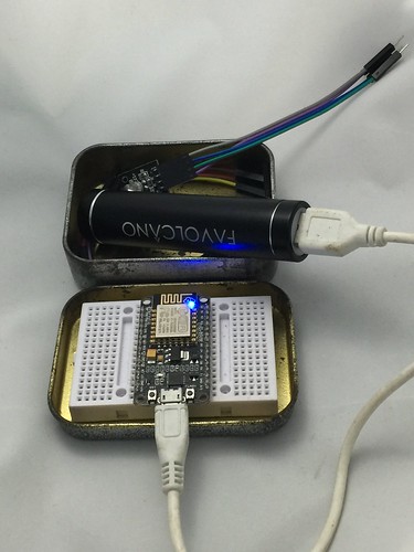 Above: The NodeMCU DevKit reference design is small enough to fit into the lid of a mint tin, but powerful enough to connect to the Internet.
Writing and uploading code
NodeMCU has some example code on their website, and there is a comprehensive documentation site for the NodeMCU Lua programming environment. I'll be posting my example projects here soon, also.
There are a number of software IDEs (Integrated Development Environments) available for editing and uploading Lua code. The quality of IDEs in the embedded world might be a little less than for mainstream computers, however I have found the ESPlorer application is serviceable, if a little quirky. It's compatible with Mac, Windows and Linux.
Most ESP modules ship with a firmware that is intended to work as a "WiFi Modem" (the so-called AT Firmware). The first thing you'll need to do is wipe this and install the NodeMCU firmware by following these instructions.
You can obtain the latest NodeMCU firmware from this service. I recommend you start with the default modules plus HTTP, I2C, MQTT, PWM and SPI. If you buy an LCD screen add the UCG module.
Once your board is running the NodeMCU firmware, there are three main ways to get your Lua application program code onto your module:
- Use a USB-to-Serial converter between your PC's USB port and the NodeMCU board's asynchronous serial interface. The NodeMCU DevKit has a built-in USB converter, so you just need a USB cable.
- Connect a Bluetooth-to-Serial module to the NodeMCU board's asynchronous serial interface, and pair the bluetooth module with your PC.
- Use one of the above methods to install a program on your board that lets you send further programs to it over WiFi.
We'll cover the first two of these methods in the next article in this series. From the point of view of your PC, they are the same, except that in the first case you are connecting to a virtual serial port implemented by the USB converter, and in the second case you are connecting to a virtual serial port implemented by the bluetooth module. USB is slightly cheaper and easier to work with, but do consider Bluetooth if you have a Mac, especially those with limited USB type-A ports.
Connecting your module to the outside world
The NodeMCU programming environment provides a number of library functions grouped into modules, and has programming modules that provide high level abstractions for many common input and output devices. Where there is no high level abstraction, the low level GPIO module provides direct access to the input output pins and allows youto write your own programs to interface with almost anything.
The NodeMCU firmware provides a number of core software modules to perform various tasks (such as read particular models of sensors, and control particular models of display), and there are even more modules availble as open source contributions that you can add to your base firmware. There are web services that will construct a new firmware image for you containing the set of modules that you select, or you may upload the NodeMCU source code, import some extra modules, and compile a firmware image that contains all the modules you desire.
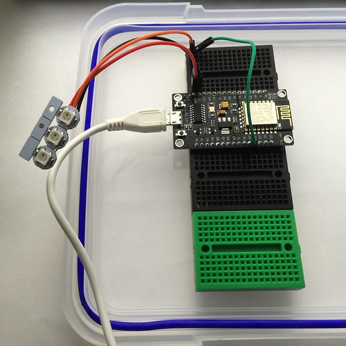 Above: NodeMCU DevKit board mounted on a solderless breadboard and connected to module consisting of three full-colour Light Emitting Diodes. On these breadboards, each socket is electrically connected to the other four sockets in its row.
Simple outputs (e.g. for Lights)
To control lights, or motor modules the gpio firmware-module can be used to set a pin to a high or low voltage using the gpio.write function. The pins on the ESP and most microcontrollers can act as either inputs ("reading" the voltage presented to the pin) or outputs ("writing" a voltage to the pin). We must set the mode of a pin with the gpio.mode function to use it as an output.
Microcontrollers don't output very much power on their IO pins, typically only just enough to light up a small light-emitting-diode (LED), so if you are controlling higher powered devices like relays or motors, you will need to use a power boosting circuit. Generally modules for relays and motors include this boost circuit so can be connected directly to your output pins.
When you use a light-emitting diode (LED) you generally need another component called a 'resistor' to set the brightness by limiting how much power may pass through the LED. Without a resistor the LED may consume too much power and burn-out. Pre-built LED modules will often include all the extra power-limiting circuitry you need.
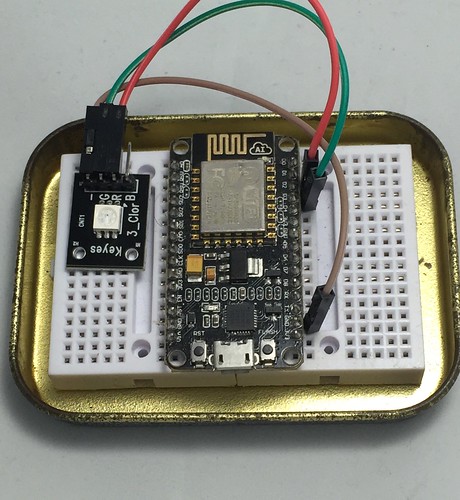 Above: A Light-Emitting Diode (LED) module connected so that it can light up red or green under control of the NodeMCU DevKit
Simple inputs (eg. for Buttons)
If you configure a pin as input by calling gpio.mode then it does not output any voltage, instead any voltage applied from outside will be reported as a logical one or a zero when gpio.read is called. When the NodeMCU environment starts up, all the pins are in input mode unless you reconfigure them in your code.
The simplest way to connect a switch is to have a switch between the pin and ground (zero volts) and to have other circuitry that presents high voltage when the switch is not pressed. The extra circuitry can be part of a switch module, or provided by the "internal pull up" circuit inside the microcontroller. Again, pre-built switch modules should include any extra circuitry that is needed.
A digital input pin is going to convert whatever voltage it sees into one of two values. Typically anything from 0 Volts up to about half of the high level will read as a zero, and anything higher than that will read as a one. Some microcontrollers can read "analog" voltage where the actual voltage is reported as a number proportional to the voltage (say converting a voltage between zero and 3.3 volts into a number between 0 and 255). We'll stick to digital inputs only here.
 Above: A button module connected to a NodeMCU DevKit
Internet access
Once we have a Thing with buttons and lights, we are ready to join the Internet Of Things, typically via wireless ethernet (WiFi)
There are four modules in NodeMCU for talking to the Internet:
- Wifi
For configuring the wifi hardware (as an access point, client, or both) and scanning and joining networks
- Net
For making network connections or implementing servers
- HTTP
For making HTTP requests or implementing servers
- MQTT
For publishing messages to the Message Queue Telemetry Transport, or subscribing to topics on a message server
As an example, one could construct an adjustable thermostat consisting of a temperature and humidity sensor, a graphical liquid crystal display, a rotary dial switch and a push-button switch entirely using off-the-shelf modules supplied as part of the NodeMCU environment.
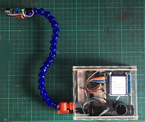 Above: A sophisticated but easy to assemble IoT project consisting of a rotary dial switch, an LCD Screen, and an InfraRed proximity detector.
See Ideas below for some more project examples.
Shopping lists
Here is what to buy to get started. I will present three lists - A basic starter set, a comprehensive but inexpensive set of modules, and some stretch options.
As I mentioned above, for the very budget-conscious, you can buy just the NodeMCU DevKit board itself and experiment with its on-board button and LED.
The item listings below are at AliExpress.com which is a Chinese electronics and consumer goods bazaar. Sometimes items go out of stock or change price unexpectedly, I'm happy to advise if you are unsure about anything.
Basic starter set
The bare minimum starter kit currently costs around US$12 if you order the recommended items below (I have no commercial interest in these recommendations):
- NodeMCU development board- $3.18
- CPU with wifi and USB interface. This has one light and one button built in.
- A 400-hole breadboard- $1.00
- This breadboard will accomodate your NodeMCU board and leave space for plugging in other modules if you so desire
- 10cm Jumper wires- $1.55
- A basic set of multi coloured jumper wires can be peeled apart singly, or in twos and threes, as needed.
- Button module- $0.95
- You probably want one or more buttons so that you can send messages to the internet. Look at the sensor kit in the next section for more input options
- Light-emitting-diode (LED) module- $0.70
- This module actually has three LEDs - one red, one green, one blue, in the same package. You can use just one colour, or mix colours.
- A USB battery - $3.91
- A rechargeable power bank is the best way to power your projects. An old phone charger works too. Consider buying locally as some countries will not accept batteries by airmail. If you don't already have a micro-USB cable, they cost around one dollar.
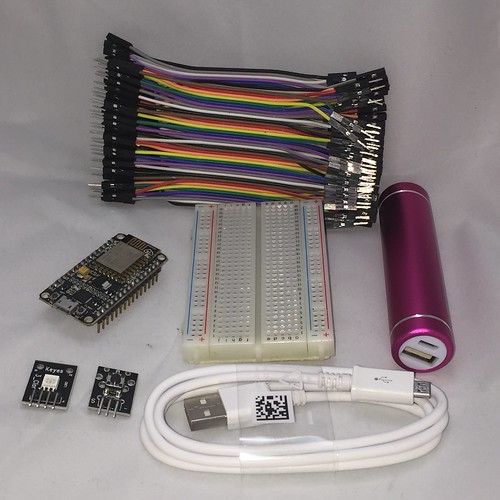 Above: all the items in the $12 basic IoT starter kit.
If you are buying for a team hackathon, consider searching for the same item plus "10pcs" or "100pcs" you will often find bulk items at an even lower cost.
A comprehensive set of Input/Output modules
Once you have a basic kit, you might like to experiment with things other than buttons and lights. A kit containing one each of practically every kind of sensor costs a little over US$10.00:
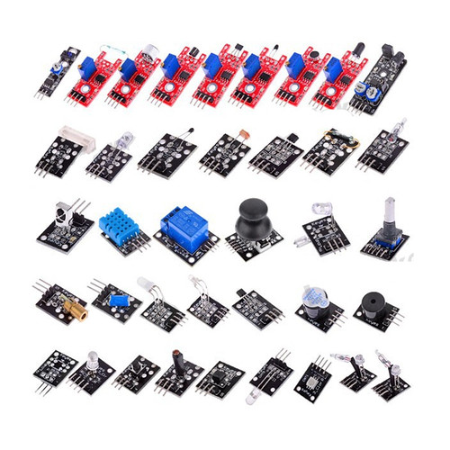 Above: A $10 sample-bag of peripheral input and output modules
So for around $20 total outlay you can be up and running with the ability to build many kinds of IoT projects.
Special extras
You might like to consider these optional extras:
- Bluetooth-to-serial interface - $2.78
- If you find plugging and unplugging USB to be annoying, or have an ultralight notebook with limited USB, you can use Bluetooth to upload to your board. You will need to buy or borrow a USB-to-Serial converter, below, to set up this module. I'll cover how to use this module in another post.
- USB-to-serial interface - $1.50
- If you have trouble finding drivers for the USB chip built into your NodeMCU module, or if you are using an ESP board that lacks a built in USB interface, the FTDI USB-to-serial converter has the best supported drivers.
- Longer jumper wires - $2.55
- Jumper cables are commonly available in 10cm, 20cm or 30cm lengths. While the shorter ones are most useful, a set of longer cables is handy to have.
- Shorter jumper wires - $1.68
- If you need to join nearby rows on a breadboard, a short wire that is exactly the right length can be neater than a jumper cable
- 128x160 LCD Screen - $3.15
- A small video screen lets you show text, graphics and menus. This screen uses the ST7735 chip that is supported by NodeMCU's ucg module.
- 320x240 LCD Touch screen - $7.62
- A larger LCD screen with touch panel, which can take the place of a whole lot of buttons. This screen uses the ILI9341 chip that is supported by NodeMCU's ucg module.
- Mini breadboards - $3.81 for 6
- These small breadboards clip together or can be stuck to a surface. Handy for modules that are too wide for a single board.
- Small breadboards and a baseboard - $3.55 and $2.82
- These boards can be snapped onto a Lego-like baseboard (not Lego compatible) which lets you arrange them exactly how you need them